Dec 182016
 

Letzte Woche gab’s Vanillekipferl. Hier das Rezept (http://www.chefkoch.de/rezepte/403911129675192/Uromas-Vanillekipferl.html). Auf die Hälfte reduziert:

  • 150g Mehl
  • 125g Butter
  • 60g Mandeln, gemahlen
  • 50g Zucker
  • Vanillezucker/Vanillearoma
  • Zum Wenden: Puderzucker, Vanillezucker

Alles mischen, in Folie gewickelt 30min in den Kühlschrank stellen. In der Zwischenzeit Puderzucker und Vanillezucker mischen und in eine verschliessbare Schüssel geben (zum wiederverwenden des Zuckers).

Kipferlteig in eine Rolle mit etwa 4cm Durchmesser rollen. 1cm Scheiben abschneiden. Daraus die Kipferl formen und recht eng aneinander auf ein mit Backpapier belegtem Blech legen. Bei 175°C ca. 20 Minuten backen.

Kurz (3 min) kühlen lassen und dann in die Puderzucker-Zucker Mischung wenden. Abkühlen lassen und in eine Dose verschliessen.


Dec 032016
 

Since I keep forgetting what pins I used for the ‘595 ICs which drive my 16 segment LED clock, here the pinout:

1: Vcc   2: GND
3: /SCK  4: NC
5: SER   6: NC
7: /RCK  8: NC
9:      10: NC

Since it’s HC595, Vcc is 2 up to 6V

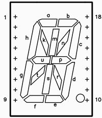
And while on this topic, the 16 segment has this order when sending a 16 bit stream:

t-s-r-n-m-k-p-u-h-g-e-f-d-c-b-a.

Bit 0 is t, bit 15 is a.

Nov 192016
 

I was looking for a recipe of something my grandma made. She called it “Gebackenes Zeug” which unfortunately is not a proper name. it contained Quark and mashed potatoes, but that’s all I knew. But today I found something which is at least similar if not identical except for the shape: Sächsische Quarkkeulchen. Here the recipe:

Zutaten für die Quarkkeulchen
500g Pellkartoffeln
500g abgetropfter Magerquark
150g Mehl
40g Zucker
70g Rumrosinen
Mark von ½ Vanilleschote
1 Eigelb
Abrieb von ½ Zitrone
Butterschmalz zum Braten
Puderzucker zum Bestäuben

Zubereitung der sächsischen Quarkkeulchen
1.    Die Kartoffeln weichkochen, pellen und durch die Kartoffelpresse drücken. Mit den restlichen Zutaten zu einem Teig vermengen.
2.    Aus dem Teig gleichgroße Quarkkeulchen formen und in heißem Butterschmalz beidseitig goldgelb ausbraten. Kurz vorm Servieren alle Quarkkeulchen mit etwas Puderzucker bestreuen.

Taken from here. Being in Japan means: no Quark, so I used Philadelphia cream cheese. I also added ascorbic acid (AKA Vitamin C) to make it a bit sour. No rainsins as I had none. No egg as cream cheese has enough fat. No lemon since I had none. And I had to use normal butter instead of clarified butter. No powdered sugar either.

So I had to change it a lot and I only used 3 potatoes and about 150g cream cheese. Turned out to be tasty though and it’s definitely similar to “Gebackenes Zeug”.

Will try again. Will make pictures then.

Nov 192016
 
Orange Pi Zero - Neat

Got myself a (actually two) Orange Pi Zero: US$7, quad core ARM Cortex [email protected], 256MB RAM, WLAN, FastEthernet, 1 USB, USB-to-go for power. All in a (about) 5×5 cm² package. Add in a 8GB microSD card, and it’s a small capable little board.

While the memory looks on the small side, itś plenty to run one program. Armbian uses about 40MB itself when running:

harald@opz1:~$ free 
              total        used        free      shared  buff/cache   available 
Mem:         247012       36720      142740        2168       67552      193175 
Swap:        131068           0      131068

leaving >200MB left. Given that I can have a (small, limited) web server runnig on an ESP8266 with about 40KB RAM, 256MB is plenty for a single-purpose server/controller.

Ethernet works (as expected). WLAN works via simple nmtui command.

Controlling the 2 LED’s is easy too:

root@opz1:/# cd /sys/class/leds/red_led 
root@opz1:/sys/class/leds/red_led# ls 
brightness  device  max_brightness  power  subsystem  trigger  uevent 
root@opz1:/sys/class/leds/red_led# echo 1 >brightness  

That turns on the red LED. Similar for the green LED.

To find out what GPIO’s exist, use this:

root@opz1:/sys/class/leds/red_led# cat /sys/kernel/debug/gpio                                              
GPIOs 0-383, platform/sunxi-pinctrl, sunxi-pinctrl: 
 gpio-10  (?                   ) out hi 
 gpio-17  (red_led             ) out hi 
 gpio-202 (xradio_irq          ) in  lo 
 gpio-354 (?                   ) out hi 
 gpio-362 (green_led           ) out hi

To export a GPIO, do

# echo 15 >/sys/class/gpio/export

and then in /sys/class/gpio/gpio15/ you can see the standard Linux kernel GPIO things like direction (in/out) and value (0/1)

See also the schematics which show what port of the H2+ connects to what thing: orange-pi-zero-schanetics-v1_11 (sp!)


Nov 062016
 

During today’s Dev Japan Meetup I finally had the time to do something I always wanted to do but never had time to implement: Create a fast link from an end-device (AKA browser or phone application) to my LED display. That display is a simple 10×10 WS2812 LEDs strip originally connected to an Arduino with a Bluetooth receiver, but replaced by a Wemos D1 mini flashed with Espruino since that has WiFi and more RAM.

Here the important (but incomplete) part of the Espruino program:

var host = "the_ws_server.co.jp";
var WebSocket = require("ws");
var ws = new WebSocket(host,{
  path: '/',
  port: 8080, // default is 80
  protocol : "echo-protocol", // websocket protocol name (default is none)
  protocolVersion: 13, // websocket protocol version, default is 13
  origin: 'Espruino',
  keepAlive: 60
});

ws.on('open', function() {
  console.log("Connected to server");
});

ws.on('message', function(msg) {
  console.log("MSG: " + msg);
  if (msg == "R") {
    colorize(40, 10, 10);
  } else if (msg == "G") {
    colorize(10, 40, 10);
  } else if (msg == "B") {
    colorize(10, 10, 40);
  }
  esp8266.neopixelWrite(NodeMCU.D4, leds);
});

The logic is as simple as it looks: connect to a WS server and wait for incoming messages. If it’s “R”, or “G”, or “B”, then colorize the LED array.

Here a section of the browser part:

var ws = new WebSocket("ws://the_ws_server.co.jp:8080/");

ws.onopen = function(evt) {
  var conn_status = document.getElementById('conn_text');
  ws.send(JSON.stringify({"join":"led"}));
};

ws.onmessage = function(evt) {
  var newMessage = document.createElement('p');
  newMessage.textContent = "Server: " + evt.data;
  document.getElementById('messages_txt').appendChild(newMessage);
};

ws.onclose = function(evt) {
  alert ("Connection closed");
};

$(".color").click(function(evt) {
  console.log($(this).attr("val"));
  ws.send(JSON.stringify({"room":"led","msg":$(this).attr("val")}));
});

and the buttons look like

<button type="submit" class="color" val="R">Red</button>
<button type="submit" class="color" val="G">Green</button>
<button type="submit" class="color" val="B">Blue</button>

The one missing part is the websocket server in the middle which relays messages, which I took quite literally from here from the Espruino Websocket docs.

This is anything but clean code, and not yet a complete and instructive example application, but it’s the first step and a good proof-of-concept.

Next step is a web page to have a 10×10 grid of buttons which can be turned on/off by touching, and the corresponding commands are sent to the LED display.
Oct 302016
 

Previously I made LEDs on/off via Lua. The pin-order was 4, 3, 2, 1, 5, 0, 6, 7, 8 in NodeMCU: 6 red LEDs, and a RGB LED.

Using Espruino (specifically version 1.87), the order turns out to be: D2, D0, D4, D5, D14, D16?, D12, D13, D15. D1 seems to turn the WiFi LED on/off, which is a bit odd.


Update:

Espruino has a nice feature to convert NodeMCU pins into Espruino pins:

for (var i=1; i<11; ++i) { console.log(NodeMCU["D"+i])}
D5
D4
D0
D2
D14
D12
D13
D15
D3
D1

Or easier, just use NodeMCU.D1 for what was D1 in NodeMCU. It also helps to know that the Espruino numbers are simply the GPIO numbers of the ESP8266 (Espruino D5 = ESP8266 GPIO 14 = NodeMCU D1)

Oct 302016
 

Lua is neat, but learning Lua and JavaScript and NodeJS. Although Lua and especially NodeMCU is similar (not only in name) to NodeJS, it would be nicer to use only one language.

Here the recipe:

  1. Download espruino_1v87.tve_master_b3dc05b_esp8266.tgz
  2. Write flash (note: might use 80m and qio, but my old one does dio):
    ./esptool.py --port /dev/ttyUSB0 --baud 115200 write_flash --flash_freq 40m --flash_mode dio --flash_size 32m \
    0x0000 ~/Downloads/espruino_1v87.tve_master_b3dc05b_esp8266/boot_v1.6.bin \
    0x1000 ~/Downloads/espruino_1v87.tve_master_b3dc05b_esp8266/espruino_esp8266_user1.bin \
    0x3FC000 ~/Downloads/espruino_1v87.tve_master_b3dc05b_esp8266/esp_init_data_default.bin \
    0x37E000 ~/Downloads/espruino_1v87.tve_master_b3dc05b_esp8266/blank.bin
  3. Verify it:
    ./esptool.py --port /dev/ttyUSB0 --baud 115200 verify_flash \
    0x1000 ~/Downloads/espruino_1v87.tve_master_b3dc05b_esp8266/espruino_esp8266_user1.bin \
    0x3FC000 ~/Downloads/espruino_1v87.tve_master_b3dc05b_esp8266/esp_init_data_default.bin \
    0x37E000 ~/Downloads/espruino_1v87.tve_master_b3dc05b_esp8266/blank.bin
  4. Connect at 115200bps.
  5. Connect to your AP:
    var wifi = require("Wifi");
    wifi.connect("your_sid", {password:"your_password"}, function(err){
     console.log("connected? err=", err, "info=", wifi.getIP());
    });
    wifi.stopAP();
    wifi.save();
  6. In the Espruino IDE add the IP address
  7. When you reconnect via Espruino IDE, you should now have 2 choices: serial or TCP/IP via WLAN


Oct 162016
 
Node-RED: Functions

My light sensor (actually just a LDR connected to the single ADC pin on the ESP8266) tends to be a bit jumpy and the graphs looked anything but smooth. Quick fix: averaging samples. Node-RED has functions for this. And here is one to average 4 samples:

// jshint esversion: 6

const oldDataMax=4;
let lastData;
let count = context.get('count')||0;
let oldData = context.get('oldData')||[];

// Need to shift all numbers one left if array full
// Circular buffer would be nice, but overly complex for such small buffers

if (count==oldDataMax) {
 for (let i=1; i<oldDataMax; ++i) {
 oldData[i-1]=oldData[i];
 }
 lastData=oldDataMax-1;
} else {
 lastData=count++; 
}
oldData[lastData]=parseInt(msg.payload);

// Calculate the average

let avg=0;
for (let i=0; i<=lastData; ++i) {
 avg+=oldData[i];
 }
avg=avg/(lastData+1);

context.set('count', count);
context.set('oldData', oldData);

let avgMsg = { payload: ""+avg };

return [ msg, avgMsg ];

Much less jumpy graphs now!


Oct 022016
 

With only one sensor, its value is as accurate as can be: I got no other value to compare to.

Since I got a BME280 and a DS18B20 and both can measure temperature, I have something to compare. Both have a quite high resolution (0.01 resp. 0.0625 degree), but less accuracy (±0.5 degree at 25°C or ±1 degree from 0…65°C for the BME280, ±0.5 degree from -10..+85°C for the DS18B20), I was curious how they compare. Here is the result:

screenshot_20161002_095312

The upper one is the BME280, the lower one is the DS18B20. Difference is about 0.75 degree.The truth is probably somewhere in the middle, but hard to say without proper calibration. Unfortunately the BME280 is  for air usage only which makes calibration against e.g. ice water or any other liquids challenging.

I have another DHT22 (AKA AM2302) sensor , which shows temperatures between above. Unfortunately its humidity sensor seems to be broken.

Sep 302016
 

Some time ago I tried to use Node-RED  but it did not work for me. Lack of reading docs I’d guess now. When I tried it again some days ago, it worked just fine and created quickly nice temperature diagrams with my nodeMCU and a 1-wire DS18B20 temperature probe.

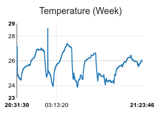
week-temperature

Here you can see the temperature over the last 4 days. The shark peak is me holding the temperature sensor. Fast temperature drops are caused by the air conditioning.

This is all with a relative accuracy of 0.0625°C. Absolute accuracy is much less. See the data sheet of the DS18B20. Or read this for fun and education about absolute calibration.

BTW, my Node-RED runs on my Banana Pi BPI-M1 (via Ethernet cable as WiFi caused instable network connections as well as full blown random crashed). MQTT server is on the cloud in a Docker container on my Linode VM.