Mar 252017
 
STM32F4 Discovery and Espruino

Some time ago I installed Espruino on the STM32F4 Discovery board.

Here my notes:

sudo aptitude install cmake libusb-1.0-0-dev
git clone https://github.com/texane/stlink.git
cd stlink
cmake .
make
# install into /usr/local/
sudo make install
sudo ldconfig -v

How you should be able to see the STM32F4 Discovery board:

$ sudo st-info --probe 
Found 1 stlink programmers 
 serial: 563f6b06493f51521236213f 
openocd: "\x56\x3f\x6b\x06\x49\x3f\x51\x52\x12\x36\x21\x3f" 
  flash: 1048576 (pagesize: 16384) 
   sram: 196608 
 chipid: 0x0413 
  descr: F4 device

and now flash:

 
$ sudo st-flash write espruino_1v91_stm32f4discovery.bin 0x08000000                                
st-flash 1.3.1-11-g78ced6a 
2017-03-25T20:41:03 INFO src/common.c: Loading device parameters.... 
2017-03-25T20:41:03 INFO src/common.c: Device connected is: F4 device, id 0x10016413 
2017-03-25T20:41:03 INFO src/common.c: SRAM size: 0x30000 bytes (192 KiB), Flash: 0x100000 bytes (1024 KiB) in pages of 16
384 bytes 
2017-03-25T20:41:03 INFO src/common.c: Attempting to write 298872 (0x48f78) bytes to stm32 address: 134217728 (0x8000000) 
Flash page at addr: 0x08040000 erasedEraseFlash - Sector:0x6 Size:0x20000  
2017-03-25T20:41:09 INFO src/common.c: Finished erasing 7 pages of 131072 (0x20000) bytes 
2017-03-25T20:41:09 INFO src/common.c: Starting Flash write for F2/F4/L4 
2017-03-25T20:41:09 INFO src/flash_loader.c: Successfully loaded flash loader in sram 
enabling 32-bit flash writes 
size: 32768 
size: 32768 
size: 32768 
size: 32768 
size: 32768 
size: 32768 
size: 32768 
size: 32768 
size: 32768 
size: 3960 
2017-03-25T20:41:13 INFO src/common.c: Starting verification of write complete 
2017-03-25T20:41:16 INFO src/common.c: Flash written and verified! jolly good!

How you should be able to see the STM32F4 Discovery board:

And here a small program which reads out the accelerometer LIS302DL and the most upper LED will be lit up. Be aware that on newer F4 Discovery boards this model has changed to LIS3DSH, which is not compatibel.

function onInit() {
 SPI1.setup({sck: A5, miso:A6, mosi:A7});
 SPI1.send([0x20,0b01000111], E3);
}

var avrx=0.0, avry=0.0;
function getAcc() {
  var accx = SPI1.send([0xA9,0], E3)[1];
  var accy = SPI1.send([0xAB,0], E3)[1];
  if (accx>127) accx-=256;
  if (accy>127) accy-=256;
  avrx = 0.1*accx + 0.9*avrx;
  avry = 0.1*accy + 0.9*avry;
  digitalWrite(LED1, avrx > 32);
  digitalWrite(LED4, avrx < -32);
  digitalWrite(LED2, avry > 32);
  digitalWrite(LED3, avry < -32);
}
onInit();setInterval(getAcc, 10);

Mar 202017
 

Bluetooth and its LE variant are new areas for me and, but the learning curve is not too steep thanks to Puck.js. Making  it do what I want is not easy though since I don’t know what it can do.

The most important documents are:

Here an example:

// Have a service to show temperature and battery level
// This is only visible when you are connecting to the Puck

var currentTemperature=E.getTemperature().toFixed(2)*100;

console.log("Temp: "+currentTemperature);

NRF.setServices({
 0x1809 : { // Health Thermometer
  0x2A6E: { // Temperature
   readable: true,
   notify: true,
   value : [ currentTemperature % 256, currentTemperature / 256 ]
  }
 },
 0x180f : { // Battery Level
  0x2a19 : { // Percentage
   readable : true,
   notify: true,
   value: [ Puck.getBatteryPercentage() ],
  }
 }
});

// Updating the temperature

setInterval(function() {
 currentTemperature += 1; // For debugging: increase temp by 0.01 degree per update
 NRF.updateServices({
  0x1809 : {
   0x2A6E : {
    value : [ currentTemperature % 256, currentTemperature / 256 ],
    notify: true
   }
  }
 });
}, 2000);

Mar 112017
 

My Espruino has colored I/O pins and since I saw this, I thought “That’s neat!”

Playing with the Orange Pi Zero and its 26 pin expansion port made me really want those colored pins as connecting things wrong can destroy ports quickly: 5V and 3.3V mixed up? Magic smoke escapes. Connected GND instead of I/O pin? 50% chance of a dead output port. Miss-counted pins and used pin 11 instead of 13…happy debugging!

The Asus Tinkerboard has it too:

but it seems this is not available without the rest of the Tinkerboard.

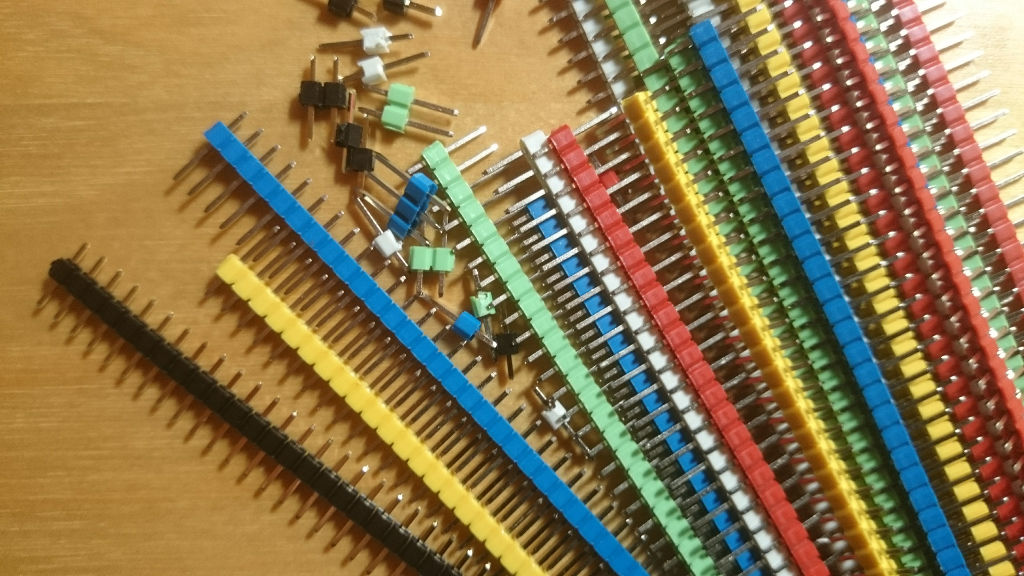
I had to build one from coloured 40 pin single row pins I got from AliExpress:

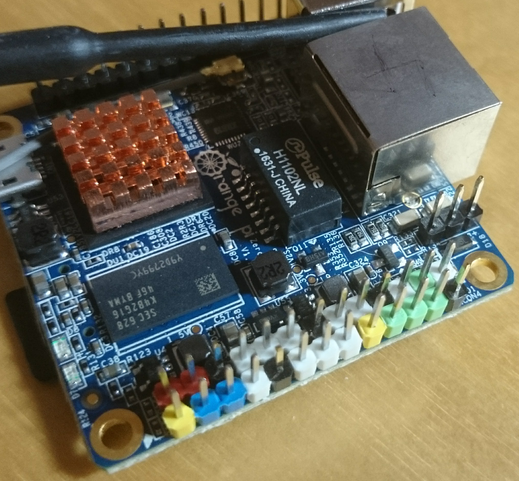
And here is the result:

Red is +5V, yellow is +3.3V, black is GND, blue is I²C and green is SPI. I don use UARTs a lot, so I did not bother to colour those.

Took about 15min of work incl. soldering. Totally worth it.

Mar 052017
 
Espruino, ESP8266 and the I2C OLED

Small Sunday afternoon project: Make the ESP8266 with Espruino work with the OLED display I have. NodeMCU has no issues. Time to try Espruino+JavaScript instead of NodeMCU+Lua.

Ingredients:

~/.local/bin/esptool.py --port /dev/ttyUSB0 --baud 115200 write_flash 
--flash_freq 80m --flash_mode qio --flash_size 32m \
 0x0000 "boot_v1.6.bin" \
0x1000 espruino_esp8266_user1.bin \
0x3FC000 esp_init_data_default.bin \
0x37E000 blank.bin
  • and then this little program will use it (if you have configured everything correctly and I2C works as it should):
I2C1.setup({sda: NodeMCU.D2, scl: NodeMCU.D1});

function start(){
 // write some text
 g.drawString("Hello World!",2,2);
 // write to the screen
 g.flip(); 
}

var g = require("SSD1306").connect(I2C1, start, {height:64});


Took me some tries to get it working and very helpful was the ability to scan the I2C bus:

function isDeviceOnBus(i2c,id) {
  try {
    return i2c.readFrom(id,1);
  }
  catch(err) {
    return -1;
  }
}

function detect(i2c,first, last) {
  first = first | 0;
  last = last | 0x77;
  var idsOnBus = Array();
  for (var id = first; id <= last; id++) {
    if ( isDeviceOnBus(i2c,id) != -1) {
      idsOnBus.push("0x"+id.toString(16));
    }
  }
  return idsOnBus;
}

I2C1.setup({sda: NodeMCU.D2, scl: NodeMCU.D1});
console.log('I2C detect as array:',detect(I2C1));

Note that I could not make the Wemos OLED work as its size (64×48) seems not supported. The 128×64 display I have worked out of the box. 128×32 is supposed to work too (see here).