Nov 062016
 

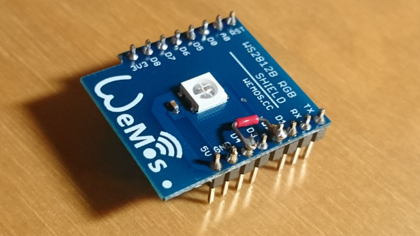
During today’s Dev Japan Meetup I finally had the time to do something I always wanted to do but never had time to implement: Create a fast link from an end-device (AKA browser or phone application) to my LED display. That display is a simple 10×10 WS2812 LEDs strip originally connected to an Arduino with a Bluetooth receiver, but replaced by a Wemos D1 mini flashed with Espruino since that has WiFi and more RAM.

Here the important (but incomplete) part of the Espruino program:

var host = "the_ws_server.co.jp";
var WebSocket = require("ws");
var ws = new WebSocket(host,{
  path: '/',
  port: 8080, // default is 80
  protocol : "echo-protocol", // websocket protocol name (default is none)
  protocolVersion: 13, // websocket protocol version, default is 13
  origin: 'Espruino',
  keepAlive: 60
});

ws.on('open', function() {
  console.log("Connected to server");
});

ws.on('message', function(msg) {
  console.log("MSG: " + msg);
  if (msg == "R") {
    colorize(40, 10, 10);
  } else if (msg == "G") {
    colorize(10, 40, 10);
  } else if (msg == "B") {
    colorize(10, 10, 40);
  }
  esp8266.neopixelWrite(NodeMCU.D4, leds);
});

The logic is as simple as it looks: connect to a WS server and wait for incoming messages. If it’s “R”, or “G”, or “B”, then colorize the LED array.

Here a section of the browser part:

var ws = new WebSocket("ws://the_ws_server.co.jp:8080/");

ws.onopen = function(evt) {
  var conn_status = document.getElementById('conn_text');
  ws.send(JSON.stringify({"join":"led"}));
};

ws.onmessage = function(evt) {
  var newMessage = document.createElement('p');
  newMessage.textContent = "Server: " + evt.data;
  document.getElementById('messages_txt').appendChild(newMessage);
};

ws.onclose = function(evt) {
  alert ("Connection closed");
};

$(".color").click(function(evt) {
  console.log($(this).attr("val"));
  ws.send(JSON.stringify({"room":"led","msg":$(this).attr("val")}));
});

and the buttons look like

<button type="submit" class="color" val="R">Red</button>
<button type="submit" class="color" val="G">Green</button>
<button type="submit" class="color" val="B">Blue</button>

The one missing part is the websocket server in the middle which relays messages, which I took quite literally from here from the Espruino Websocket docs.

This is anything but clean code, and not yet a complete and instructive example application, but it’s the first step and a good proof-of-concept.

Next step is a web page to have a 10×10 grid of buttons which can be turned on/off by touching, and the corresponding commands are sent to the LED display.

Sep 222016
 

I bought a small waterproof DS18B20 based temperature probe. Finally I had a reason to use it: to measure the temperature drop in the joeveo mug which I received 2 days ago. While the theory is sound, it’s one thing to just believe in it or to measure yourself. I pick the latter, especially if it it involves some programming!

Temperature over time for various things

x: time in seconds, y: temperature in degrees Celsius

Using flot (for now) to make a quick graph, I got a sense of temperature drop in my normal ceramic mug as well as an idea of the drop in an insulation mug. The first graph (ice melting in glass) was using integers for the temperature.  The DS18B20 can clearly do better, so the next measurements I did with the floating point NodeMCU firmware.

Here the trivial code:

ds18b20 = require("ds18b20")
gpio0 = 3
ds18b20.setup(gpio0)

# plot temp over time

mytime0 = tmr.time()
n = 0

function plot_temp()
 uart.write(0, "["..tmr.time()-mytime0..","..ds18b20.read().."],")
 n = n > 4 and 0 or n+1
 if n == 0 then
  print()
 end
end

tmr.alarm(0, 10000, tmr.ALARM_AUTO, plot_temp)

Integrate the output into a HTML et voilà: a simple yet good looking graph.

Step 2 is to actually measure the temperature in the joeveo mug.


Aug 202016
 
Power Usage of Wemos D1 mini + WS2812B RGB Shield

Using the Wemos D1 mini + WS2812B RGB shield + Battery shield and a 750 mAh single cell LiPo from my Walkera Dragonfly V120D02S , I wondered how long it’ll last to run. It’s not super-low power (use Bluetooth for that, not Wifi), but anything from 1h to 24h was possible according to my estimates and absolute power rating limits. So it’s time to measure!

The conditions:

  • ws-to-tcp bridge in my PC bridges the raw TCP port with a WebSocket port which is what the JavaScript web page uses which can change the LED color.
  • Lua program runs listening on a TCP socket. Nothing else runs actively.
  • When a command comes in via the TCP socket, analyze the command and execute it. Estimated run time: less than 10ms.
  • To confirm all keeps on working, I changed the LED color about 4 times per hour.
  • The LED was set to run at 20% R, G and B (brightness 55 out of 256).
  • The set of battery shield, D1 mini and LED shield and the battery had no other connections to the outside world.

Results:

  • Run time: 14h (750mAh LiPo from fully charged via battery shield, to 3.45V)
  • Average power draw for the LiPo: 700mAh/14h=50mA (assuming 700mAh used)
  • Assuming 90% efficiency of the DC-DC circuit (see TP5410 datasheet), that’s about 30mA@5V coming out of the battery shield (it only feeds +5V)
  • Average power consumption by LED: 55/256*3*20mA=13mA@5V (plus whatever the LED controller chip uses)
  • Leaving 17mA for the D1 mini. The LDO RT9013 drops that to 3.3V (still 17mA)
  • No sleep mode was used here since the device is listening to a TCP port.

The efficiencly is obviously improvable (going from >3.3V to 5V and then to 3.3V again for the ESP8266).

Side note: Charging is taking about 1h until the call has 4.195V. Very nice. I’ll see what the cell voltage is when the TP5410 shuts down. According to the data sheet, it’s likely 2.7V (undervoltage protection).

Update a day later:

With the WS2812 LED being on with low intensity, here the result:

  • Run time: 20h
  • Voltage of LiPo: 2.7V at the end
  • The TP5410 of the battery shield turned off 5V, but the 5V rail still had voltage to make the red and green LEDs of the WS2812 glow (blue turned off)
  • The ESP8266 was still rsponsive via WiFi. Its blue WiFi LED got significantly fainter compared to before when the LiPo was full.
  • Using the same assumptions as above:
    • 21mA@5V out of the TP5410
    • LED board: <1mA @ 5V, for the LEDs
    • About 20mA for the D1 mini module

This is consistent with the first measurement and good enough for me. For a day of being online, you need 1Ah single cell LiPo for the CPU/battery module.

This list shows 15mA for Modem Sleep State and 50mA and more for active WiFi connections. The conclusion would be that NodeMCU uses Modem Sleep when listening to incoming TCP packets.

Aug 142016
 

When you have a microcontroller which can connect to the network and it has a RGB LED, the logical step is to make this LED controllable via a web browser.

The list of issues faced is numerous:

  • NodeMCU does not handle websockets natively
  • Thus a bridge between normal TCP sockets used by NodeMCU and WebSockets used by the web browser is needed: ws-tcp-bridge does that
  • ws-tcp-bridge defaults to binary blobs which the browser cannot handle. Switching the websocket’s binaryType to arraybuffer fixes this
  • Sending data too fast to a just created websocket which has its binaryType not yet changed to arraybuffer breaks ws-tcp-bridge with a fatal error:
    TypeError: “list” argument must be an Array of Buffers
  • NodeMCU uses Lua, the browser JavaScript. The langages are quite similar! See below for an example.

Code is at https://github.com/haraldkubota/rgbled-websocket

Interesting is the comparison of Lua and JavaScript variable names are the same):

JavaScript Lua
for (c of s.split('')) {

  if (c>='0' && c<='9') {
    if (state==1)
      value=10*value+c.charCodeAt()-48;

    } else {
      if (state==1) {
        setOneColor(color, value);
        state=0;
      }
      if (c=='R' || c=='G' || c=='B') {
        color=c;
        value=0;
        state=1;
      }
   }
}
for n=1,s:len(),1 do
   c=s:sub(n, n)
   if c>='0' and c<='9' then
     if state==1 then
       value=value*10+c:byte(1)-48
     end
   else
     if state==1 then
       setOneColor(color, value)
       state=0
     end
     if c=='R' or c=='G' or c=='B' then
       color=c
       value=0
       state=1
     end
   end
 end


Aug 132016
 

2 more I/O shields: Temperature and humity sensor (DHT22 AKA AM2302) and here the super-simple example:

print(dht.read(4))
0 26 1 800 0

That’s 26.8 °C and 1.0% humidity. I somehow don’t trust the humidity…

And here the push button module example, which shows well how much the contact bounce is:

do
 local pin=3
 gpio.mode(pin, gpio.INT, gpio.PULLUP)
 local pulse1=0

 local function pushed(level)
 local pulse2 = tmr.now()
 print("Level: ", level, "since last change: ", pulse2-pulse1, " ns")
 pulse1=pulse2
 end
 
 gpio.trig(pin, "down", pushed)
end


Aug 132016
 

It was surprisingly difficult to find some working nodeMCU examples. Thus here my findings and sample code:

First the WS2812 shield: It’s using D2 (NodeMCU numbering, which is printed on the board). The ws2812 module for NodeMCU uses D4 though. Here what it looks like:

Wemos-WS2812-modified

With this change, this sample program works:

ws2812.init()
ws2812.write(string.char(100, 20, 5))

Green 100, Red 20, Blue 5. GRB.

The OLED shield needs no hardware modification, but it’s using non-standard I²C pins it seems. Here a working example (using a very slightly modified https://github.com/nodemcu/nodemcu-firmware/blob/master/lua_examples/u8glib/u8g_graphics_test.lua).

I removed the SPI parts, adjusted the pins. The rest is unmodified:

-- ***************************************************************************
-- Rotation Test
--
-- This script executes the rotation features of u8glib to test their Lua
-- integration.
--
-- Note: It is prepared for SSD1306-based displays. Select your connectivity
-- type by calling either init_i2c_display() or init_spi_display() at
-- the bottom of this file.
--
-- ***************************************************************************

-- setup I2c and connect display
function init_i2c_display()
 -- SDA and SCL can be assigned freely to available GPIOs
 local sda = 2 -- 5 -- GPIO14
 local scl = 1 -- 6 -- GPIO12
 local sla = 0x3c
 i2c.setup(0, sda, scl, i2c.SLOW)
 disp = u8g.ssd1306_64x48_i2c(sla)
end


-- the draw() routine
function draw()
 disp:setFont(u8g.font_6x10)
 
 disp:drawStr( 0+0, 20+0, "Hello!")
 disp:drawStr( 0+2, 20+16, "Hello!")

 disp:drawBox(0, 0, 3, 3)
 disp:drawBox(disp:getWidth()-6, 0, 6, 6)
 disp:drawBox(disp:getWidth()-9, disp:getHeight()-9, 9, 9)
 disp:drawBox(0, disp:getHeight()-12, 12, 12)
end


function rotate()
 if (next_rotation < tmr.now() / 1000) then
  if (dir == 0) then
   disp:undoRotation()
  elseif (dir == 1) then
   disp:setRot90()
  elseif (dir == 2) then
   disp:setRot180()
  elseif (dir == 3) then
   disp:setRot270()
  end

  dir = dir + 1
  dir = bit.band(dir, 3)
  -- schedule next rotation step in 1000ms
  next_rotation = tmr.now() / 1000 + 1000
 end
end

function rotation_test()
 print("--- Starting Rotation Test ---")
 dir = 0
 next_rotation = 0
 print("size:", disp:getWidth(), disp:getHeight())
 local loopcnt
 for loopcnt = 1, 100, 1 do
  rotate()

  disp:firstPage()
  repeat
    draw()
  until disp:nextPage() == false

  tmr.delay(100000)
  tmr.wdclr()
  end

 print("--- Rotation Test done ---")
end

init_i2c_display()
rotation_test()

The important bits: SDA=2, SCL=1, ADDR=0x3C (there’s a jumper to change it to 0x3D if needed)


Aug 132016
 
Wemos D1

Got some new NodeMCU modules: Wemos D1. Very neat small modules with USB and “shields”, one of them being a 0.66″ I²C OLED display with 64×48 pixel. Very cute.

I needed some extra NodeMCU modules (specifically 1-wire and u8g), so a new firmware was in order. Best place for that is http://nodemcu-build.com/. Highly recommended.

One odd problem I saw though: when using the usual

./esptool.py --port /dev/ttyUSB0 --baud 115200 write_flash 0x0 
~/Downloads/nodemcu-master-20-modules-2016-08-13-01-27-33-integer.bin

to program the FLASH, all I got is a stream of data on the serial port after a reset and not the usual prompt. Power cycle did not change that behavior. Neither did waiting. Even re-programming esp_data_init_default.bin did not help. What did help is adding the -fm and -fs parameters:

./esptool.py --port /dev/ttyUSB0 --baud 115200 write_flash -fm dio -fs 32m 0x0 
~/Downloads/nodemcu-master-20-modules-2016-08-13-01-27-33-integer.bin

The interesting bit is that programming an older image from about a month ago worked fine without -fm and -fs. Which made me think there’s something buggy in the creation of the image (e.g. the new modules I added are broken).