18 January 2020
This blog is moving to a new home: https://hkubota.wordpress.com/
My old blog is reachable here: https://blog-static.harald.workers.dev/wordpress/index.html
Comments
This blog is moving to a new home: https://hkubota.wordpress.com/
My old blog is reachable here: https://blog-static.harald.workers.dev/wordpress/index.html
Reading about Zink (not the chemical element, but the printing technology) made me wonder how well this can work. It seems to be incredible to get proper colors out of this method:
The yellow layer is the topmost one, sensitive to short heat pulses of high temperature. The magenta layer is in the middle, sensitive to longer pulses of moderate temperature. The cyan layer is at the bottom, sensitive to long pulses of lower temperature. The layers are separated by thin interlayers, acting as heat insulation, moderating the heat throughput.
This is radically different from normal printing technologies and thus it's worth checking out in more details.
So I got myself one of those Zink printers: a Canon iNSPIC (AKA Canon Ivy in US AKA Canon Zoemini in Europe). Canon seems to like to change product names depending on the region. Weird. Confusing. But once identified which one is which, I can get an English driver/manual for a Japanese product. And of course the opposite too.
Reason for the Canon as opposed to the many other Zink printers: the quality of the software, the availability, and the price of the Zink media: About 2000 Yen for 50 photos. For HP Sprocket I'd have to pay 2700 Yen for 50. For Polaroid Zip I'd pay 2800 Yen for 30.
A quick run-down: Charge printer for 30min, install the Canon app on my phone, connect via Bluetooth, pick a photo, adjust it (zoom, crop, add text), and print. I see why the Canon app is popular: it works and most buttons do what you think they do. So far some prints showed that the resolution and colors are ok. Black is solid black. Photos look ok. Of course colors are not calibrated, but neither is my phone nor my computer monitor.
I'll use this printer mainly as full color label printer. I got quite some boxes of unknown content. Well, unknown until I open them. Maybe with this thing I can create more expressive labels.
I guess I cannot avoid using Python. As much fun as Node.js is and as much as I like the ability to do work in the background, a lot of my simpler scripts use async/await which reduces the program to simply do its work one line at a time. And in order.
Python on normal Linux machines is way too boring. Running it on an ESP32 is far better: I got plenty examples using Espruino (JavaScript), so I can use those to re-program them in MicroPython. Should be easy, right?
./esptool.py --chip esp32 --port /dev/ttyUSB0 erase_flash
./esptool.py --chip esp32 --port /dev/ttyUSB0 --baud 460800 write_flash -z 0x1000 esp32-20190125-v1.10.bin
You should now be able to connect to /dev/ttyUSB0 (115200 bit/s) and get the Micropython REPL. Get the ESP32 binary from here. esptool from here.
ampy is used to upload and run Python programs on your microcontroller.
pip install adafruit-ampy --user
Now you can do things like showing the internal flash filesystem:
ampy --port /dev/ttyUSB0 ls
export AMPY_PORT=/dev/ttyUSB0
ampy ls
ampy get /boot.py
def do_connect():
    import network
    wlan = network.WLAN(network.STA_IF)
    wlan.active(True)
    if not wlan.isconnected():
        print('connecting to network...')
        wlan.connect('sauerkraut2', 'AntonAnton')
        while not wlan.isconnected():
            pass
    print('network config:', wlan.ifconfig())

do_connect()
Save this as a file (e.g. wlan.py). Replace WLAN SSID and PASSWORD of course:
$ ampy run wlan.py
network config: ('192.168.22.219', '255.255.255.0', '192.168.22.1', '192.168.22.1')
So the ESP32 connected to the WLAN and got an IP 192.168.22.219!
Obviously at this point you want to see the microntroller do something you cannot do by your main Linux (or Windows) machines. E.g. link a LED. Or write something on the OLED. I happen to have an128x64 OLED with a SSD1306 controller, so I'll use that. Here the program taken from here from Lauri Võsandi (call it esp32-oled-demo.py):
from time import sleep_ms
from machine import Pin, I2C
from ssd1306 import SSD1306_I2C

buf = "wubba lubba dub dub  "

i2c = I2C(-1, Pin(4),Pin(5),freq=40000) # Bitbanged I2C bus
assert 60 in i2c.scan(), "No OLED display detected!"

oled = SSD1306_I2C(128, 64, i2c)
oled.invert(0) # White text on black background
oled.contrast(255) # Maximum contrast

for j in range(0, 500):
    oled.fill(0)
    oled.text(buf[j%len(buf):]+buf, 10, 10)
    oled.show()
sleep_ms(40)
However it needs the ssd1306 module, which you can get like this:
wget https://raw.githubusercontent.com/adafruit/micropython-adafruit-ssd1306/master/ssd1306.py
and then you upload it to the microcontroller:
ampy put ssd1306.py
Now you can run your program from above:
ampy run esp32-oled-demo.py
Espruino devices do not usually have a proper battery-backed RTC available, so the second easiest way to get a time is via (S)NTP. On Espruino on the ESP8266 this is super-simple (192.168.21.1 is my NTP time server and 9 is the timezone offset):
//ESP8266
//Wifi.setSNTP("192.168.21.1", 9);
but that does not work on Espruino on the ESP32 as Wifi.setSNTP() does not exist here (nor anywhere else). But a module for SNTP exists. This is how to use it to set the time:
// ESP32
E.setTimeZone(9);
const sntp=require('sntp');
var options = {
    host: '192.168.21.1',
    port: 123,
    timeout: 1000
};

sntp.time(options, function (err, time) {
    if (err) {
        console.log('Failed: ' + err.message);
        return;
    }
    setTime(time.T2/1000);
    //console.log('Local clock is off by: ' + time.t + ' milliseconds');
    //console.log('Full NtpMessage:', time);
});
Way more complicated, but it's more general on Espruino.
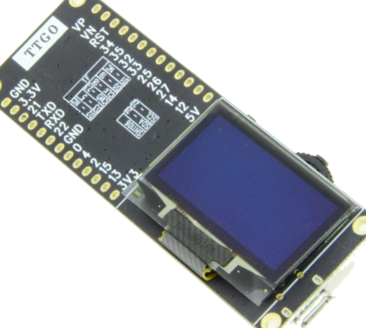
TTGO T-Eight is a small ESP32 board from here. Small OLED, left/right/select input method, microSD slot, and 4 MB PSRAM, LiPo connector, plus of course WiFi/Bluetooth is a good combination of features. The problem as usual is the lack of documentation. The situation is even worse in this particular case:
Anyway, here is what I found:
So here a small minimal Espruino program which uses the display and which can read the buttons:
// TTGO T-Eight

I2C1.setup({sda: 21, scl: 22, bitrate: 400000});

function gstart(){
 g.drawString("Hello World!",2,2);
 g.flip();
}

// I2C
var g = require("SH1106").connect(I2C1, gstart, {height:64});

// g.clear(); g.drawCircle(50, 32, 30); g.flip();

// Note: pushing will trigger several times (for repeat: true)
// Need to software de-bounce

setWatch(function(e) {
console.log("Right");
}, D37, { repeat: false, edge: "falling"});

setWatch(function(e) {
console.log("Click");
}, D38, { repeat: false, edge: "falling"});

setWatch(function(e) {
console.log("Left");
}, D39, { repeat: false, edge: "falling"});